Suitable for alternative firing of mineral fuel oil according to DIN 51603 as well of gas with characteristics as listed.
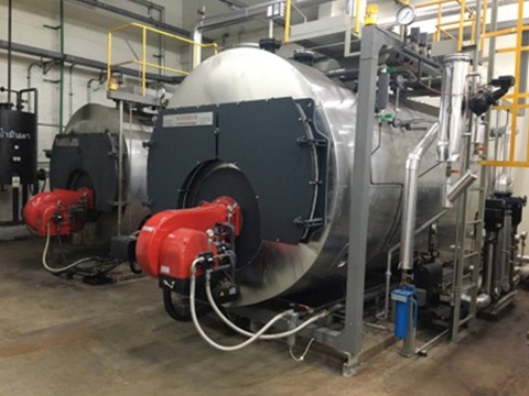
“RAY” oil & gas combination burners of the BGEC series are industrial duo-block burners. They combine the oil and gas burner. They are modular, based on the building block principle and consist of the burner, an air reservoir, the separately installed blower and the fuel feed line and control.
The series is suitable for parallel or separate combustion of all technical fuel gases as well as gas and all mineral heating oils and combustible liquid waste materials. The control unit used as standard ensures that oil/gas is used sparingly and makes it easier to operate and maintain the burner. All essential functions such as fuel and air supply or flame monitoring are controlled with precision. Due to the modular burner structure and the resulting flexibility, they can be used for a large number of special applications. Individual project planning, a short planning phase and high system availability are guaranteed. The use of the RAY oil/gas combination burner allows a free choice of fuel for economic or operational reasons.


Burner in Monoblock construction, can be hinged open to the left or the right, type of protection IP54, type tested, approval to EN676.
“WEISHAUPT” produces gas and oil-fired boilers, heat pumps, and burners. These top-quality products are characterized by their meticulous development, high-quality workmanship, outstanding operational reliability, and maximum Efficiency. Their unrivalled excellence extends equally to design and function.
Weishaupt WM-series oil, gas, and dual-fuel burners are equipped as standard with electronic compound regulation and digital combustion management. Modern combustion technologies demand a precise and continually reproducible dosing of fuel and combustion air. This is the only way optimal combustion figures can be ensured over extended periods.


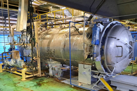
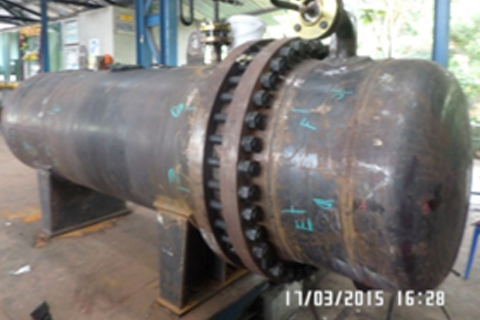
Self-contained unit, ready for operation. Heating surfaces and headers made of stainless steel tubes, ribs of aluminium. The heat exchanger has been subjected to a pressure test at 21 bar. All materials exposed to high temperatures are of special heat resisting quality.
NOTE : MATERIAL SELECTION FOR AIR HEATERS (FOOD GRADE)
ABSTRACT FROM THE EUROPEAN REGULATION (EC) NO 1935/2004

 PLC Interface overview
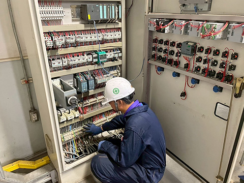
 PLC–SYSTEM FOR SMART CONTROL
 SCADA
SCADA


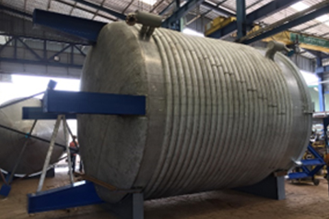
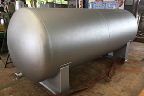
 Tank farm


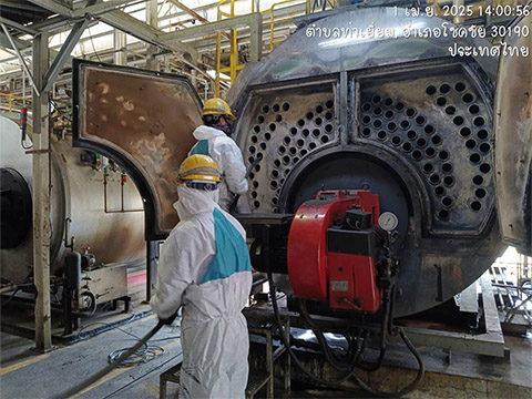
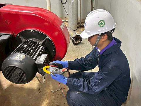
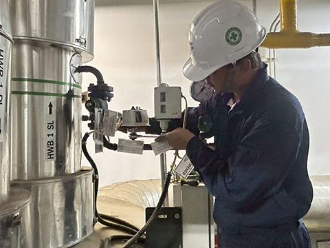
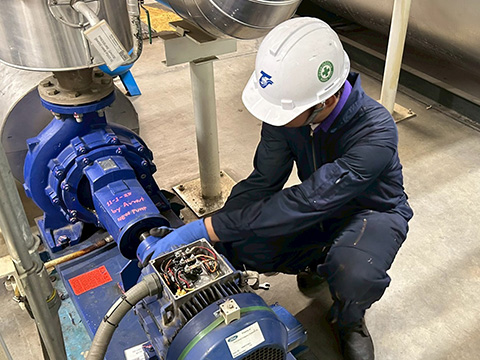
Annual inspection to issue safety certification for steam & hot oil boiler under Thai laws and regulation for:

Preventive Maintaining of steam & hot oil boilers regularly under condition: